

[From: Davis, Paul D., "The Breakthrough Breadboard Feasibility Model: The Development of the First All-Transistor Radio", Southwestern Historical Quarterly, July 1, 1993, v.97, n.1, pp.56-80].
The Development of the First All-Transistor Radio
Introduction by DIANA KLEINER
Contrary to images that associate the state primarily with cotton, oil, and cattle, Texas has played a major role in the development of high technology for four decades. Some of the most technologically and commercially important advances in transistors, computers, and microelectronics have been made here, many of them by Texas Instruments Incorporated (TI). The following essay by former TI engineer Paul D. Davis provides a personal account of one of these developments: the creation in May 1954 of an engineering feasibility model for the first all-transistor radio at the firm's Dallas laboratory and manufacturing division. Following this design breakthrough, the firm began production of the first all-transistor portable radio in October of that year.
In May 1954 TI general manager Patrick Haggerty committed two million dollars to a secret crash research project, asking his engineers to design and build a prototype of the new technology in time to meet a potential buyer's deadline. The successful "breadboard model" Davis describes is an example of the early engineering practice of literally strapping new electronic circuitry to household breadboards to facilitate design changes. The result was the Regency TR-1 radio, which reached stores by November and sold for $49.95. For Haggerty the effort was less a matter of proving that an all-transistor radio was feasible than of showing Tom Watson of IBM that TI could manufacture transistors in quantity, and was therefore a company to be reckoned with in the new semiconductor industry.. According to legend, Haggerty knew he had achieved his objective when an IBM executive bought several of the radios and distributed them to other company officials.
Before it entered the semiconductor field, TI was known for the manufacture of oil equipment and military defense devices. Physicists Clarence "Doc" Karcher and Eugene McDermott founded the firm in 1924 at Tulsa as the Geophysical Research Corporation (GRC), a subsidiary of Amerada Petroleum, to develop seismic equipment for locating oil deposits. Seeking a freer business climate than Amerada could provide, GRC, which quickly became the region's leading geophysical exploration firm, established an independent company in Dallas in 1930 known as Geophysical Service, Inc. (GSI), which in turn set up its first research and development laboratory in Newark, New Jersey. The company located so much oil that in 1938 its owners founded a spin-off company, the Coronado Corporation, for the sole purpose of finding oil. Coronado was sold in 1940, and in that year company employees bought GSI.
The next stage of development was initiated by J. Erik Jonsson, who moved to Dallas from the Newark lab in 1934 and encouraged the firm to apply echo-tracking techniques used in locating oil to develop defense-related location devices for the military. Jonsson's timing was perfect, and the company became a key military electronics supplier in World War II. After the war, Patrick Haggerty, a visionary ex-Navy procurement officer and electrical engineer from Washington, D.C., took over as general manager and oversaw the construction of a lavish new GSI plant. Renamed General Instruments in 1950, the company became Texas Instruments in 1951 when the Pentagon objected to the similarity between "General Instruments" and the name of another supplier.
TI turned to transistor development after a Bell Telephone team of semiconductor physicists including William Shockley, Walter Brattain, and John Bardeen invented the technology in 1948. In 1951 TI paid Bell a $25,000 license fee to become one of the first companies in the nation to manufacture transistors. Willis Adcock and Gordon Teal, who left Bell Labs to mass-produce less expensive and more reliable transistors, went to work for TI to create a silicon transistor, which they achieved in 1954, though not in time for the Regency TR-1. Another innovation came in May 1958 when TI's Jack St. Clair Kilby developed the integrated circuit. Today TI produces geophysical and industrial products, electrical and electronic devices, military equipment, metallurgical products, nuclear fuel elements, and industrial supplies.
Paul D. Davis grew up in Dallas, trained at Southern Methodist University, served in the Navy, and worked at the Watterson Radio Manufacturing Company of Dallas before joining TI in 1948. The development of the first all-transistor radio feasibility model occurred at the firm's new laboratory and manufacturing center on Lemmon Avenue near Love Field in Dallas. There, TI employed between 100 and 200 workers to manufacture Navy equipment, design prototypes, and service geophysical equipment. According to Davis, the atmosphere at the lab was relaxed and intimate, though the climate was influenced by the Navy background of many staff members and the engineers were used to working on deadline. The standard work week included Saturday mornings. Haggerty took the first packaged model of the radio to the I.D.E.A. Corporation of Indiana for manufacture because, like modern "switchboard" corporations which use smaller companies to supply research, manufacture, or sales and distribution components as needed, TI had no consumer marketing division at the time. The company's next application of transistor technology produced an inexpensive electronic calculator, another harbinger of the computer era.
The event Davis describes from his insider's perspective marked the beginning of the global competition in semiconductor chip manufacture that continues today, and a "second industrial revolution" which, like the first, reduced the drudgery of labor. In this instance, computer technology replaced the labor of computation rather than manual labor. The story of the "breakthrough breadboard" also demonstrates an early effort at "managed" or "planned innovation," a process first articulated by Thomas Edison, who promised to produce a new invention every six months at his New Jersey laboratory. By the 1990s, this idea was part of a management strategy commonly employed to increase the speed with which new developments were made. Innovation has been described as the integral or sum total of advances in a product's creation, whether invention, manufacture, or marketing. Conventionally associated with research and development in the physical sciences, the best example of an innovation in manufacture is Ford's assembly line, which exponentially increased the speed of production. In an article published in the 1980s, Haggerty explained that TI then employed seventy-seven intracompany "strategies" and 591 "tactical action programs" to maximize innovation. Rather than rely on large laboratories dedicated to systematic research, future corporate R&D may revert to the smaller, more flexible model of the TI lab in the 1950s to respond more quickly to management demand and to convert new technologies more rapidly into marketable applications.
At about 4 P.M. on Friday, May 21, 1954, I received a call in the Dallas engineering lab at Texas Instruments to come upstairs to the office of the company manager, Pat Haggerty. Pat's office had windows on the west, facing Lemmon Avenue, and the venetian blinds were closed to block out the bright afternoon sun. In the subdued light of the office, I could see Pat, my boss Jim Wissemann (the chief engineer), and a few other management-level people.
Pat got right to the point. He said that he was assigning me to head a special project to develop an all-transistor radio -- the first such design capable of being produced in large quantities.
As Pat was talking, I could not help but feel some excitement. My background was in the field of radio, in the Navy and as design engineer for the Watterson Radio Manufacturing Company of Dallas, and this appeared to be an opportunity to return to my favorite type of electronic equipment.
The transistor was invented in 1948 by scientists at Bell Laboratories, and in 1951 TI was licensed as one of the few companies to develop and produce these radically new electronic components.
You often hear the transistor referred to as a "solid-state" device, and sometimes as a "semiconductor." This simply means that it is made of solid materials, such as germanium or silicon, through which flow the electric currents it controls. Vacuum tubes, on the other hand, are not solid-state devices, because the controlled currents flowing through them must pass through a vacuum inside the tube.
In the early 1950s the TI engineering group with which I was associated was assigned to work on circuit design projects for equipment which would utilize transistors, these new miniature, low-power-consumption, rugged devices which were destined to replace vacuum tubes. But at the time of that meeting in Pat's office available transistors were capable of operating only at low frequencies, such as those used in power system control circuits, hearing aids, and audio amplifiers -- frequencies below 20,000 cycles per second (cps). Except for a few costly laboratory units, no transistor manufacturer had yet been able to design a transistor which would amplify the much higher radio frequencies of 50,000 (sic) cps (500 kilocycles per second) and above.
To design and build a transistorized radio, we needed low cost radio frequency (RF) transistors capable of operating over the broadcast band from 550 kHz to 1600 kHz. TI was developing such high-frequency transistors, and the company felt it was well ahead of the rest of the semiconductor industry in being able to produce such devices, especially in the large quantities that would be needed for a mass-produced radio. To vividly demonstrate the company's leadership in new transistor design, Pat pointed out that it was TI's intention, in parallel with completing the development and initial large-scale production of these new RF transistors, to develop a pocket-sized, all-transistor radio that could be mass-produced and sold to consumers in the very near future.
It was made clear that the full resources of the Semiconductor Department would be available to support the radio design project. This included the technical support of the semiconductor design group under Dr. Willis Adcock, an outstanding pioneer in development. They would supply our radio development project with the latest RF transistors, and we would test them in actual circuits which we would design. Working as a team, we would supply each other design and test result data on a daily (or even hourly) basis, and thus speed up work on both projects.
Pat further explained that the initial goal of our project was to develop a "breadboard" feasibility model transistorized radio that was fully operable over the broadcast band from 550 to 1600 kHz, comparable to vacuum tube radios in sensitivity ("station-getting" ability) and sound output, and capable of being packaged in a pocket-sized case.
The feasibility model would be used to demonstrate to an established consumer radio manufacturing company that TI could produce and supply RF transistors in the immediate future. It was expected that the radio manufacturer would then, without delay, begin producing the first transistorized radios, and they would contain TI transistors exclusively. This would help prove to the world, especially the world of companies which use transistors, that little-known (at that time) TI was a leader in the semiconductor business and a desirable source for advanced design versions of such components.
I was informed that I could choose anyone at TI I wished to have assigned to the radio development project. Without hesitation, I selected Roger Webster as the lead design engineer. He had been a key designer and had done an excellent job on several recent low-frequency transistor circuit development projects. For example, Roger had developed a transistorized version of a vacuum tube device for the Army in less than three months, which a whole team of engineers at a competing company had been unable to do in a year's time. Two other engineers chosen for the original breadboard feasibility model radio design team were Ed Jackson and Mark Campbell. Both were part of the staff of the Semiconductor Division at TI and were experts in both transistor and circuit design.
At the time, it was generally understood throughout the electronics industry that efficient RF transistors, and thus transistor radios, would be available in quantity some day, but some day was at least several months, or even years, in the future. And here Pat had determined that TI was going to do it right away. I could envision that with hard work we could have a radio in perhaps four to six months, thus scooping the competition by perhaps a year or more. But when I asked Pat when we should have the feasibility (breadboard) model ready, he said matter-of-factly, "I don't need it until next Wednesday, when our potential client will be here." My next move, of course, was to rush downstairs and get the team organized so we could start work on the project that very evening.
As TI engineers, we were accustomed to meeting tight schedules on development projects, like a goal of six months for a product where most companies would have a goal of at least a year. TI engineers seemed to thrive on such projects. Such dedication comes easily when one has a respected leader like Pat, himself a hard worker and an innovator who relished a challenge, both as a manager and as an engineer. But to develop and build a working model of a transistorized radio in four days (and nights) when one had never been conceived (much less designed), the transistor types to be used had not yet been tested in RF circuits, and the
It was scary, even for these experienced engineers used to "impossible" schedules. Nevertheless, there was no hesitation on their part that Friday afternoon, even though they could see no clear solution to the many unique problems associated with designing transistor circuits that would operate at radio frequencies. We not only did not know the solutions, we did not even comprehend all the problems that lay ahead. Not exactly your typical Friday afternoon.
In setting up the transistor radio design project, one of the first things Roger, Ed, Mark, and I did that Friday evening was to calculate gain (amplification) characteristics requirements for each section of the radio -- the radio frequency as well as the audio frequency amplifiers. This helped us to set the design goals, or specifications, for each section of the radio.
In order to acquire a small tuning condenser and a small speaker, both needed for the radio we were to design, we purchased the smallest available tube-type radio, an Emerson, first thing on Saturday morning. From it, we could remove and use those unusually small parts not readily available from parts supply houses. Other key parts which we would need for the transistor radio, especially transformers, we would have to design and fabricate ourselves. This small tube-type radio was six inches wide, three and a half inches high, and one and a quarter inches deep. It was called a pocket radio because it could be carried in the pocket of a large overcoat, a major achievement in the miniaturization of vacuum tube radios. Such radios required two relatively small, short-life batteries. One was a one-and-a-half-volt flashlight type called an "A" battery. It was used to supply current to light the filaments of the tubes. The other battery was a miniature forty-five-volt type called a "B" battery. It supplied the other currents, called "plate" circuit current, needed for the tubes to amplify the received signals.
Our measurements of the operating characteristics of the small tube radio, before removing the tuning condenser and speaker, confirmed our calculated gain requirements which would have to be designed into the various stages of the transistor radio to achieve an adequate signal output. This signal output would have to be high enough to give an undistorted, easy-to-hear sound across a normal-sized room. We were now ready to get on with our design tasks.
We decided to use the proven superheterodyne circuit principles and divided up the circuit design responsibilities. The superheterodyne-type radio circuit is divided into four sections. The first section consists of a circuit to tune in the desired station RF signal frequency. This section also contains an oscillator (called a local oscillator, or LO) to generate a second signal, which is added to the first RF signal in a mixer to convert the RF frequency to a lower RF frequency, called an intermediate frequency (IF). The second section is the IF amplifier, followed by a third section which detects or removes the audio frequencies riding "piggy-back" on top of the RF frequency. The final section is the audio amplifier, which builds up the audio signal enough to drive a loudspeaker.
Roger agreed to take on the toughest assignment, the design of the IF amplifier -- toughest because it required a circuit which would amplify radio frequency (RF) electrical signals by a factor of many thousands. Not only would new transistors capable of handling such high frequencies have to be used for the first time in an easily reproducible circuit, but all related circuits and components would have to be designed "from scratch." These circuits would not only require unique performance characteristics, but, to assure that the radio would be pocket-sized, they also had to be subminiature in size, one-fourth to one-tenth the size of even the smallest equivalent vacuum tube circuit components.
Ed took on the tasks of designing the output stages and audio frequency amplifier and providing direct assistance to and coordinating with the semiconductor scientists who were designing and fabricating the special new transistors which would be needed. Mark Campbell and I agreed to work on the design of the input and mixer circuits. It was also my job to coordinate the efforts of the group and locate and procure those special components which we weren't forced to fabricate ourselves, as well as seek help from other departments of TI as needed.
For the IF amplifier design, Roger decided to use the frequency 262 kHz, lower than the usual 455 kHz. Remember, at that time amplification at any RF frequency using transistors was very difficult, and the lower the acceptable frequency the better the performance one could expect. Also, most vacuum-tube automobile radios used 262 kHz IF amplifiers quite satisfactorily.
Without going into the technicalities, the primary reason for using a higher IF frequency is that it reduces the chances for interference between two stations, one operating near the top end of the AM band and the other operating near the low end of the band. However, the chances for such interference can also be greatly reduced by using better, more selective circuits at the input, as did automobile radios and as we planned to do.
The design team made a preliminary estimate of the amplification (gain) requirements for each stage, or section, of the radio. How much total amplification must the radio have in all its stages to assure that the extremely small RF current picked up by the antenna/input tuned circuit is built up to a signal level that will operate a loudspeaker? For a typical small radio receiving relatively strong local stations and having an audio output of a "listenable" (not loud) level, the RF signal input power is so small that amplification must be on the order of 100 billion times. What is a "listenable" level of audio signal power into a loudspeaker? Someone has said it is enough to cause a sound level out of a small speaker equal to the sound from a tom cat when you step on his tail -- not the power from a present-day jukebox or from a "boom box," but enough to be heard easily throughout an ordinary room. Typically, about one-tenth of a watt of electrical audio frequency signal into a small speaker is sufficient.
Back to the "100 billion times" amplification requirement: such big numbers are obviously hard to handle in making the calculations required in designing circuits. However, there is a smaller, simpler term to express gains involving large numerical values: the decibel (dB). In designing circuits of the types used in radios, TV, audio amplifiers, etc., to simplify calculations, engineers use this special unit of measure in place of the huge numbers for watts of power gain. In such nomenclature, for example, 110 dB is the same as a power gain of 100,000,000,000 (or 100 billion) times. So from here on I will be using dB to denote gain or amplifications.
The design team determined that it would be desirable to provide at least fifty dB of the gain in the radio's IF amplifier stages. It is very important in designing any radio that a large part of the overall gain (amplification of the desired signal) be accomplished in the "front end" RF stages, ahead of the detector/audio amplifier stages. The reason for this is that the larger the amplified RF signal, and thus the audio signal out of the detector, the less background "noise" will be heard.
When you turn up the volume of an AM radio tuned off station, you hear a loud hissing or crackling noise. Normally, this is the inherent electrical "noise" present in the atmosphere. However, the gain of the early transistors was so low and their inherent noise was so high that transistor noise would dominate the radio performance, degrading (lowering) the signal-to-noise (S/N) ratio. This problem would be compounded in a very small radio because the ferrite core antenna would be quite small, thus limiting its ability to "pick up" the radio signal. This means that such a radio could be used only for listening to powerful, nearby stations whose RF signals could overpower the RF noise in the input stages. (Even from a sensitive and well-designed radio, you can hear some background "noise" when you try to listen to a weak signal from a distant station. In this case the signal from the station is too weak to overcome the relatively high atmospheric "noise.")
Consequently, to build a "practical" transistor radio, and a pocket-sized one at that, the "front end" amplifier stages must use transistors which produce high signal gain at RF frequencies while at the same time generating low levels of "noise." This gives what is known as a high S/N ratio. The RF and IF stages must also use circuits which are "sharply tuned" to the desired radio signal. Such sharply tuned circuits are said to have a "High Q."
To summarize the problem facing our design team, for our radio to achieve the desirable level of S/N, it meant, first, that we had to have transistors which would generate low internal noise while giving high gain at RF frequencies. Second, the tuned circuits which were to go with these transistors had to be designed for high efficiency in passing only the desired RF signal while rejecting all others (i.e., they had to be sharply tuned), thus maintaining a high S/N ratio.
Also, these circuits had to be unusually small in size in order for the planned production model radio to be pocket-sized. The largest components to be designed into the tuned circuits were transformers, but "High Q" and small size were not then compatible features in RF transformer design, especially transformers for tuned circuits operating at 265 kHz. Up until that time, RF and IF transformers were wound on thin, insulated tubular forms, with air being the primary core material. Laminated metal cores, which can reduce the size of low-frequency transformers, cannot be used at RF frequencies because they tend to "absorb," or short out, most of the RF energy current in the transformer coils.
Even though the smallest possible transformers were desirable, the coils needed for the RF input and mixer circuits were not as much of a problem as the IF transformers used to couple the IF stages. This is because, even with air core coils, as a result of operating at much higher frequencies, the RF coils could still be quite small. Thus, Roger would still have another tough problem facing him, even if he were able to obtain the promised RF transistors and design basic tuned circuits to "match" their characteristics. These would have to be far different from circuits used with vacuum tubes inasmuch as transistors then available were low impedance devices, in the range of a few ohms to a few hundred ohms (an ohm is an electrical unit for measuring impedance to current flow), whereas tubes were high impedance devices, in the range of millions of ohms. This great difference presented a challenge in designing the IF transformers, but it was not as serious a problem as one other: the tendency of transistor IF amplifiers to become unstable and oscillate (create unwanted signals) even when the circuit impedances were property matched.
We anticipated that this instability would be caused by a factor similar to that which caused instability problems in early vacuum tube RF and IF amplifiers. The problem resulted from unwanted oscillation signals, called parasitics, generated by signals being coupled from the output of the tube back to the input. Such feedback is caused by inherent "coupling capacitor" effects due to the proximity of internal elements of the tube.
Roger was fully aware that, once he designed optimum IF transformers, he would probably face similar "parasitic oscillation" problems, because transistors are three-element devices, as were most vacuum tubes at the time. He kept that potential problem in mind as he proceeded with the basic task of designing an optimum IF transformer which would help squeeze out every bit of gain possible from the new, first-generation RF transistors to be used in the RF stages.
The air is full of "radio waves" of all kinds, especially in and near large cities. There are electromagnetic RF signals from radio and TV stations and from police and industrial communications radio transmitters. Also, there is static, or unwanted RF signals, from atmospheric conditions, power lines, electrical appliances, and motors -- the list goes on and on. All of these combine to cause electrical signal interference, because such signals have a tendency to be "picked up" by the circuit components and cause unwanted electrical noise that interferes with the specific RF signal used to test a circuit under development. This unwanted RF interference was something Roger had to get away from in designing his IF amplifiers and Mark and I had to get away from in designing the mixer and RF front-end stage of the radio. (At least we were not bothered with microwave ovens in those days -- a major source of radio and TV interference today.)
The most common method for
eliminating interfering RF signals is to test circuits in a "shielded room."
This is a special room designed to shield out the unwanted signals. A shielded
room has walls of sheet copper or copper mesh screen, with soldered joints to
seal off all outside interference. Also, it is completely grounded, i.e.,
connected via heavy wire conductors to a buried ground rod or, rods. Even the
door for entering the room must be completely covered with copper screen
material, with all joints made "electrically tight" by spring brass seals when
the door is closed. The room is actually a sealed metal box, with even the
ceiling and floor covered with copper screen material.
Fortunately, TI had such
a room immediately available. Our screen room was rather small -- approximately
eight feet by eight feet by seven feet high. With test benches, test equipment,
and chairs, there was little room for people. Consequently, Mark and I would
take turns with Roger in testing our designs, with Roger's times considerably
longer than ours because of the increased complexity of his circuits. Ed
required no screen room for designing his audio amplifier. He simply had to keep
his distance from audio frequency noise generators such as AC power transformers
and electric motors.
For maximum efficiency (high gain), a transformer-coupled
transistor amplifier must have a transformer whose electrical impedance on the
primary (input) winding matches the output impedance of the transistor
supplying the signal to it. Likewise, the transformer output winding impedance
must match the input impedance of the transistor following it. These impedances
at the IF frequency were fairly easily determined by laboratory measurements of
the transistors' characteristics. Designing an IF transformer which had the
desired impedance was made difficult because it also had to be small. Our goal
for a pocket-sized transistor radio required that the IF transformer,
including the shield can surrounding it, be under 0.15 cubic inches.
At that
time, efficient IF transformers for most vacuum tube radios were about three
cubic inches in size (one inch square by three inches tall), although the
specially designed aforementioned pocket-size, tube-type radio did have
transformers that were reduced to about 0.4 cubic inches in size. This smaller
size was a result of using the then-new technology of powdered iron cores
in place of conventional air cores for the
windings (coils wound on plastic or cardboard forms). Although Roger was
acquainted with emerging component technology which would allow him to further
reduce the IF transformers to the desired size, the parts were not immediately
available, so he decided on the next best thing for the first feasibility
breadboard radio. He decided to utilize readily available coil and shield can
components in his attempt to design transformers which would match the
transistor impedance requirements.
By Saturday night, Roger had arrived at a design, fabricated, and performed preliminary tests of small (0.4 cubic inches) IF transformers in a transistor amplifier circuit. Using a signal generator to feed the IF frequency current into the amplifier, it appeared to approach the desired gain of 25 dB a stage. However, it was difficult to measure and impossible to use because the dreaded parasitic oscillations showed up shortly after any signal was applied to the input transistor.
What was he to do to stabilize the amplifier and eliminate the parasitic oscillations? He simply designed compensating circuits to feed back small, out-of-phase signals from the amplifier output to its input, much the same as was done in the old triode tube circuits described previously. This solution sounds easy now, but it was far from easy at the time because of the radically different impedances involved and the relatively small size of the components.
Once Roger had the parasitic oscillation under control in his breadboard model IF amplifier, his next task was to work with Mark and me on interfacing the output of our RF input/mixer circuit with the input of the IF amplifier.
While Roger was designing and building the IF amplifier, Mark and I had been designing the tuning circuit, or "front end," of the radio, i.e., the input/mixer stage. We first had to obtain a transistor from the semiconductor group for the mixer circuit, one that was capable of amplifying signals (RF electrical currents) at frequencies up to 1610 kHz, the top frequency of the AM radio band. (Actually, this transistor had to be capable of operating at frequencies up to 1872 kHz, as we shall see later.) We were able to acquire such a transistor with the help of the transistor engineering and manufacturing people by selecting units which had the smallest base layer in their three-layer (emitter-base-collector) crystal structure, and then testing them in an RF amplifier test circuit, which allowed us to find the ones with the highest gain. Actually, all the time we were designing the radio circuits, semiconductor personnel, under the direction of Dr. Adcock, were experimenting with various methods for "doping" the germanium crystal material and for achieving the thinnest possible base layer, both of which were key to maximizing the RF frequency gain characteristics of the resulting transistors.
The antenna input coil tuned circuit was little different from that used in a tube-type radio. The primary difference was that the relatively high-impedance tuned circuit, which normally can connect directly into a high-impedance tube's input, posed much the same problem Roger faced in matching components in the IF amplifier. This matching of impedance of the RF (antenna) coil to the mixer transistor was optimized for RF frequencies which would be tuned to when covering the AM radio band, 550 kHz to 1610 kHz.
The oscillator (signal generator) to supply the second input signal to the mixer required the design of an optimum oscillator coil to match the transistor's relatively low impedance. After experimenting with several coil designs, Mark came up with one which appeared to work properly with a selected RF transistor, one which gave a small LO signal output, tunable up to 1872 kHz. This corresponds to tuning the radio to 1610 kHz, the top frequency in the AM band, because when the mixer stage takes the 1610 kHz station signal and the LO 1872 kHz signal and mixes them together, the output is a difference of 262 kHz, the IF frequency. Note that the mixer transistor thus has to be able to handle frequencies up to 1872 kHz, not just 1610 kHz.
When the RF tuning capacitor across the antenna coil is rotated to change the value of its capacitance it selects a station on a particular frequency, say 820 kHz, the tuning capacitor across the LO coil must tune the LO to 1082, or 262 kHz above the station frequency. And so on, all across the AM band, the LO must "track" the frequency of the stations being tuned in.
One problem Mark and I had with our mixer circuit was checking it to see how well it was really working and whether or not it "tracked" properly. We were confident, by observing signals out of the mixer on an oscilloscope, that we were getting the mixing action we desired. However, the output signal consisted of various frequencies in addition to the desired IF (or "difference") frequency. This included the initial RF frequency (corresponding to the radio station signal), the LO frequency, and various harmonics (multiples) of same. Of course, what we needed was an amplifier with built-in tuned circuits to act as a filter, one that would accept and amplify only the IF frequency we desired to see and measure, and reject all others. In the absence of a laboratory instrument designed to do that, an ideal filter-amplifier would have been the IF amplifier tuned to 262 kHz. Of course, because Roger was still working on the IF amplifier, we did not have the tuned IF circuits to feed into. So, we did the next best thing with what was available; we took an old vacuum-tube portable radio, disconnected the tube mixer circuits and tied our transistor mixer's output to its IF amplifier's input transformer. We retuned our LO to track 455 kHz (instead of 262 kHz) above the station frequencies because the tube radio's IF operated at 455 kHz. After a few adjustments, we found we had an acceptable transistor tuner, inasmuch as this "hybrid" radio was able to pick up local radio stations as well as it had with its tube type input/mixer circuit. This was in spite of the mismatch between the transistor mixer's low impedance output and the tube radio's high impedance IF transformer input. At least it worked well enough to give us confidence that we had something which would probably work in a transistor radio, once all the other radio circuit designs were complete.
For a tuning capacitor on this breadboard model mixer circuit, we used the smallest one available at the time, the one from the Emerson vacuum-tube portable. It, like most radio tuning capacitors, actually had two variable condenser (capacitor) sections, one for tuning the input circuit to the station being received, and the other for tuning the LO, a frequency always 262 kHz higher than the frequency of the station received.
By Sunday evening Mark and I were ready, as was Roger, to try and marry up the first transistor radio's two key circuits, the input/mixer and the IF amplifier. There was no way to know for sure that we would not encounter some new parasitic oscillations and heaven knows what other weird goings on. Our Tuesday deadline was rapidly approaching, so we had no choice that evening but to start the "wedding" immediately.
Ed had been working quietly alone and had come up with an audio amplifier circuit design that was complete and ready to be transferred from his breadboard to the yet-to-be-completed radio's breadboard. For increased audio power output with minimum power drain on the radio's battery, he used what is known as a Class B, push-pull arrangement of two transistors as the output stage to drive the loudspeaker. This final stage of a radio (or audio amplifier, TV, etc.), being the one which must supply the power output, itself consumes more power from the power supply (battery) than the other amplifier stages. Consequently, it is important to find ways to minimize the battery drain, while maintaining adequate audio frequency (signal) current out to drive the speaker. The audio output stage was coupled to the speaker through a specialty constructed audio-frequency transformer which Ed had designed.
That Sunday evening, Roger took the RF/mixer stage which Mark and I had designed and the audio amplifier circuit which Ed had designed and began to combine them with his IF amplifier to build a complete, all-transistor radio. He laid all the parts out on a wooden board (this breadboard model was to be literally on a board). The board was a piece of one-inch by eight-inch pine about twelve inches long, and the parts were laid out in a manner that allowed easy access for interconnecting wiring.
Roger first wired the IF circuit components together and checked this circuit for proper performance. Next, he connected the RF/mixer circuit to the IF amplifier, and then the fun began. First, he had to contend with parasitic oscillations which, after a short time, he was able to clear up with some adjustments in feedback compensation circuits and by reorientation of critical components relative to one another. In designing any radio, one has to be careful in both the orientation and the location of the radio frequency components relative to one another. Otherwise, the signal currents can be picked up from one to the other in such a way as to cause spurious oscillations which block out the desired signal. On a new circuit layout, the experienced designer locates such components in a way that knowledge of component characteristics tells him or her that the unwanted "cross-feed" of signals should be at a minimum. But usually some final "tweaking" (slight reorientation) of parts is necessary to eliminate the problem signals completely. This final operation can sometimes consume an inordinate amount of time.
Fortunately, our group's experience in circuit design (and a little bit of luck) helped us minimize the time required to tie the RF/mixer and IF circuits into a "stable marriage" arrangement that Sunday evening. The overall gain of these two sections of the radio still was not quite up to our design goal, but we knew of several things to try to rectify the problem.
When we left for home that night, we were feeling pretty good about our chances of having a complete working breadboard model radio by the Wednesday deadline. After a few hours rest, the engineers were back in the screen room early Monday morning working on improving the gain of the RF/mixer and IF stages of the breadboard model. Because of his overall design experience and his recent experience in designing the IF stage, Roger took the lead in this effort. By careful selection of transistors with improved RF gain characteristics (which the TI Semiconductor Department was supplying almost hourly) and by slight modifications to the IF transformers, Roger had what we all considered to be an RF/IF arrangement with suitable gain by mid-afternoon.
The next step was to connect the detector at the output of the IF amplifier to Ed's audio amplifier breadboard. For a speaker, we used the small two-and-three-quarter-inch speaker from the Emerson tube portable. We had relatively little trouble integrating the audio amplifier into the radio, so by that evening we had a complete breadboard model radio operating in the screen room.
Despite the fact that the signal from the test signal generator in the screen room indicated that the radio was working properly, we could not help but be a little apprehensive when we took it out of the RF shield room into the world outside. Would it really receive, amplify, and detect radio station signals? Well, of course it did. Looking back, though, we were not as jubilant as we probably should have been. I suppose that, since we were engineers used to designing new circuits week in and week out, at that time it seemed more or less like just another breadboard completed. I wish we had fully realized the significance of the project and had taken photographs and had kept more detailed records.
Our "engineering breadboard feasibility model transistor radio" utilized eight transistors: one mixer, one local oscillator, two IF amplifiers, one detector, and three in the audio amplifier.
Although we had a working model, before we showed it to Pat Haggerty we wanted to review the design thoroughly and make certain all circuits were working as well as we could make them perform. On Monday evening and a good part of Tuesday, we did just that.
By late Tuesday afternoon, we felt we had the set working about as well as possible. It was quite sensitive, as indicated by how clearly it received all local AM radio stations, and the tone quality of the audio was quite good. Ed even designed a clever "mini-bass reflex chamber" for the speaker to make the sound even better, but we decided against using it in order to keep everything as simple as possible. The important thing was that we had a "Breakthrough Breadboard," a feasibility model which proved that the first transistor radios could be produced.
That afternoon, May 25, 1954, Roger and I went upstairs to Pat's office to show him the breadboard radio. Pat was the kind of manager who put great faith in engineers and did very little direct checking on us during the course of a project of this sort. Although we knew he was extremely interested in how we were doing, we had seen very little of him in the past three days. Of course we hoped he would be pleased with what we had come up with. And after he saw and operated the radio, he was very pleased and appreciative of what the design team had accomplished.
Pat then gave us a brief rundown on the plans for the radio. An executive from a small radio manufacturing firm was coming in the next day to discuss the possibility of manufacturing the first production-model transistor radio, and a pocket-sized model at that. The plan was to see that the first transistor radios on the world market would utilize TI transistors. In order to assure that would take place, our company needed not only to be the first to fabricate RF transistors in large quantities, but also to design a feasibility model radio to prove that they would perform satisfactorily. Our breadboard model had done just that. Pat later informed us that his meeting with the potential manufacturer went quite well, thanks in part to the presence of our model.
On Wednesday morning Ed, Roger, Mark, and I went back to the projects we had been working on prior to the design "fire drill" of the past few days. We were exhausted from the long hours and looked forward to getting back to our normal ten-hour days. But the "fire drill" was not over yet.
On the Saturday morning following our delivery of that first breadboard model transistor radio to him, Pat came by my office next to the engineering lab. He again stated how much he appreciated our efforts on the radio and added that he felt it was a pretty good design. In fact, he said that it was good enough that he wished to show it to some people at an important out-of-town meeting he was to attend on the coming Tuesday. Then he dropped the bomb shell: of course, he could not take along the radio in its breadboard configuration -- it would need to be neatly packaged in an attractive case for easy transport and demonstration. I knew what was coming next. He said that he would appreciate it if we could reconfigure the design into a neat package radio in time for him to take it with him Monday evening. Of course, I agreed to get the team on it right away, though I didn't even know where some of them were that morning.
I located Roger right away in the lab and soon tracked Mark down in the semiconductor building. I finally located Ed at home. When he came to the phone, I learned that he had been packing his car for a trip (to the Gulf Coast, I believe).
Shortly after noon, we had the team back together. The first order of business was to decide what the configuration of the package should be and how to go about making it. We hastily agreed on two things, given our forty-eight-hour time frame: we would use as many component parts from the breadboard model as possible, and we would use an available case for the "package."
The best available case was the red plastic case from the Emerson vacuum-tube radio. It was quite small for a first "packaged breadboard" model, but we decided to go with it for several reasons, in addition to its ready availability. First, the breadboard model's speaker and tuning condenser could be easily fit into the case, inasmuch as that is where they came from in the first place. Second, a first demonstration model mounted in a case this size would be a big step toward showing that our goal of a shirtpocket-sized (five by three by one and a quarter inches) radio was possible.
But how could we possibly package an eight-transistor radio in a space formerly occupied by a four-"peanut tube" radio? First, Roger would have to reduce further the size of his IF transformers, and everyone would have to reduce the size of the circuits. We all set about doing just that, but we soon realized that we needed an experienced mechanical engineer to coordinate our packaging efforts. For this job, I called on Harry Waugh, who was just as crazy as we were when it came to tackling projects with "impossible" schedules. He worked closely with us in fabricating a "support arrangement" for the radio's components, not really a chassis in the true sense of the word. Harry also took on the task of designing and fabricating a miniature on-off switch when we realized that conventional switches would never fit in the space available.
By Sunday afternoon, Roger had designed and fabricated the miniature IF transformers, about one-third the size of the "semi-miniature" ones used in the breadboard radio. He accomplished this by judicious use of the then-new ferrite materials, both in the core of the coils and in "cups" of the material surrounding them.
Also by Sunday afternoon, Harry had fabricated his new miniature switch and had readied the case as far as possible to receive the radio circuit components as they became available.
By early Sunday evening, Roger was in the screen room absorbed in getting his new IF amplifier with miniature transformers "peaked up" prior to its installation with other components in the case.
I recall feeling a little guilty that evening when I told the team I needed to slip away for a couple of hours to run over to Fort Worth. My brother Nick was graduating from Texas Christian University, and I certainly didn't want to miss that. Everyone agreed I should take off; besides, the screen room was getting too crowded.
When I returned that evening, Roger had his new IF amplifier operating in a stable manner, and he was ready to install it in the plastic radio case along with all the other circuits. Roger and Harry performed that operation before leaving for home. After some limited rearrangement of components to reduce the tendency to oscillate, preliminary tests indicated to us that the set was operating properly. We would begin full testing of the IF together with the rest of the "packaged" radio circuits the next morning.
We got an early start Monday morning because, although it had appeared on the previous evening that the packaged radio was going to work okay, we wanted as much time as possible to test and "peak it up" before delivering it to Pat that afternoon. By noon, Roger had completely aligned (tuned) all circuits to their optimum settings and had the radio "tracking" over the whole AM band, i.e., receiving stations equally well at all frequencies from 570 kHz to 1600 kHz.
I should add that this second radio used seven transistors instead of the eight used in the first model. Roger had substituted a diode for the transistor in the audio detector stage, with no deterioration in performance. Also, I should note that both radios used a small twenty-two-and-a-half-volt battery for a power source. This battery was about the same size as the small nine-volt batteries now commonly used in small radios, smoke alarms, etc.
Of course, Pat was pleased to receive the radio that afternoon, in time for him to carry to his East Coast meeting with interested parties the next day.
Again, we engineers went back to our regular projects, but this time we all realized that the transistor radio project would be an ongoing one for some time, and that we should expect to be called on to work on the next phase at any moment. And the next step was not long in coming, though we little realized that it would lead to a revolution in consumer electronics.
Although the transistor radio project was temporarily put on hold as far as an engineering program was concerned, TI management and marketing people were very active over the next few weeks in working out plans and agreements with the I.D.E.A. Corporation of Indianapolis. I.D.E.A. wanted to build and market the first mass-produced transistor radio, and TI wished to have its transistors in those first radios. TI's coordinator for this effort was S.T. (Buddy) Harris, TI's marketing manager, who took a very personal and active role in the program.
We learned in late June that TI would work with I.D.E.A. on a joint project to finalize the design for a production-model radio, with manufacture of the first units to begin in October. This meant, of course, that final design must be completed in just a few weeks so that manufacturing, tooling, and planning could start as soon as possible.
By this time, we had a new electrical engineer on our staff, Jim Nygaard, who had been a summer employee in the past and who had just graduated from college. When the radio design project cranked up again, Roger, Jim, and I continued on the engineering phase of the program and technical coordination with I.D.E.A.'s project engineer, Dick Koch.
One of our first actions with I.D.E.A. was to take the "red box" model radio, remove it from its case, and experiment with ways to simplify it. The primary aim was to reduce the number of components needed, and thus reduce costs. We traveled to Indianapolis to work with Dick and the other project people there to arrive at the production-model design in the shortest time possible.
On the first evening of our visit to I.D.E.A., we had our engineering model radio in the lab getting ready to make some further measurements of the performance of the various stages to help in determining where trade-offs and simplifications could be made in future models. Before this work got started, I asked Roger to use the lab RF generator to tune the radio to exactly 820 kHz, Then, I took the set outside under a starlit, summer sky, away from nearby obstructions, and turned it on. Sure enough, it was station-break time, and the first thing I heard was the cowbell trademark and the announcer saying loud and clear that we were listening to WBAP 820 from Fort Worth, Texas. That was the first time that I had attempted to find out how well the radio performed on receiving other than local stations. Hearing the familiar sounds of WBAP so clearly from hundreds of miles away convinced me that we really had something to sell.
After a couple of days at I.D.E.A. I returned to Dallas and resumed work on my regularly assigned projects. Roger continued to be TI's technical representative on the radio design project and, with Jim's help, provided liaison with Dick Koch during the engineering phase of the program that summer.
Most of the time, Roger and Jim were in Dallas, working with the TI semiconductor scientists, especially Frank Horak. While the final configuration of the radio was being designed, Frank continued to make slight modifications in the structure of the RF transistors in order to improve even further the RF characteristics of the units to be produced in large quantities. This required much screen room time for Roger and Jim, because they evaluated these very latest transistors in circuits. This way they could make any necessary changes in the transformer designs and assure peak overall performance (gain) from the IF amplifier. They coordinated their findings with Dick, mostly through frequent trips to Indianapolis by Jim. This assured that when manufacture of the radio started, circuits used would be designed for maximum performance with the latest production-type transistors.
To keep the costs down, the engineers finally came up with a four-transistor model, which was labeled the Regency Model TR-1. One transistor was eliminated from the initial design by combining the mixer and LO circuits into a one-transistor configuration, a design concept of Dick's. Further reduction in the number of transistors was accomplished by the increased gain of the IF stages and by using only one transistor in the audio section. Although the latter reduced the audio power output from that of the initial design, it still proved to be quite adequate for a small radio, and was easily heard across even larger rooms.
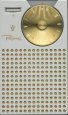
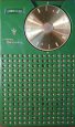
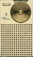
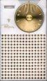
The Regency TR-1 did go into production as planned in October 1954, and thousands were sold before Christmas at a price Of $49.95. In fact, the popularity of the radio, one of which is on display at the Smithsonian in Washington, was so great that demand far outstripped supply for several months. About 100,000 were eventually produced.
In response to the requirements for producing the Regency TR-1 miniature radio, component suppliers began developing whole new lines of small components for use in transistor circuits. These included miniature low-voltage capacitors, extremely small low-wattage resistors and potentiometers, miniature variable capacitors (tuners), miniature transformers, and small but efficient loudspeakers. The availability of such miniature components led to and accelerated the development of many other types of transistorized equipment common today, including low-power TVs, VCRs, cordless phones, and cassette recorders.
Roger wrote an article on how to design IF transformers for transistor circuits, and it was published in a leading electronics magazine. The article turned out to be a classic: it became so popular that Roger received inquiries about it from radio designers all over the world for many years after it was published.
The present article is intended primarily to tell the engineers' story of those first few days of endeavor to design and fabricate the feasibility breadboard model of a transistor radio, a model that was to lead to the first transistor radio on the market. I'm sure that Roger, Jim, and Dick could tell some good war stories and greatly expand on this summary of the Hoosier Connection phase of the program and the engineering that went into the launching of the Regency TR-1, and maybe some day they will do just that.
Because almost all transistor radios have been imported for many years, most
people, including a certain network news reporter, are under the impression
that the Japanese, specifically Sony, developed the first transistor radio. Not
so! The first commercially successful transistor radio, and a pocket-sized model
at that, was developed and placed into production by engineers right here in the
U.S.A. in 1954. Sony did not produce its first transistor radio until a year
later, and their first pocket radio was not marketed until the spring of 1957.
[Paul D. Davis is a native of Nevada, Texas. He
received a B.S.E.E. from Southern Methodist University and attended Navy schools
at Bowdoin College and the Massachusetts Institute of Technology for specialized
training as a radar officer before being assigned to serve in the Philippines
during World War II. He spent thirty-six years as a design engineer, project
engineer, and branch manager at Texas Instruments. He wishes to thank Roger
Webster for reading and critiquing the original manuscript, and, along with Jim
Nygaard and Ed Jackson, helping to jog his memory.
Diana Kleiner is a research
associate on the Handbook of Texas revision project. She holds a Ph.D. in
American civilization from the University of Texas at Austin, where her
dissertation focused on the early managers who followed the founders of major
American businesses.]
 These web pages on the Regency TR-1 were created and updated for many years by Dr. Steve Reyer, who passed away in 2018. He was a true enthusiast in the radio hobby and is greatly missed. Steve was Professor Emeritus (Electrical Engineering) at the Milwaukee School of Engineering. He earned his Ph.D. in electrical engineering at Marquette University. Steve had hobby interests in consumer electronics and in Milwaukee Architecture. We are honored to keep his extensive efforts in the hobby alive and available here at collectornet.net
Copyright © 2019-2021 collectornet.net